Call Now
+91 939-332-2500
Email
sales@rsarora.com
Engineed as a specialized unified structural unit vulcanized under extreme heat and pressure. These high-grade polychloroprene blocks facilitate controlled elastic deformation to accommodate translation and rotational shifts in bridge superstructures.
Fully compliant with the latest regulatory bridge amendments.
Meets Clause No: 2005 specifications for road & bridge works.
International standard validation for use in high-impact railway bridges.
To prevent structural degradation from low-temperature environmental exposure and maintain a reliable, long-term shelf life, the raw elastomer material matrix used across all structural bearings is limited strictly to specialized raw Poly-chloroprene compounds. We utilize authenticated runs matching the following precise formulations:
Minimum overall content of pure **Poly-Chloroprene** compound in total mass.
Strictly capped maximum limit on structural **total ash content** values.
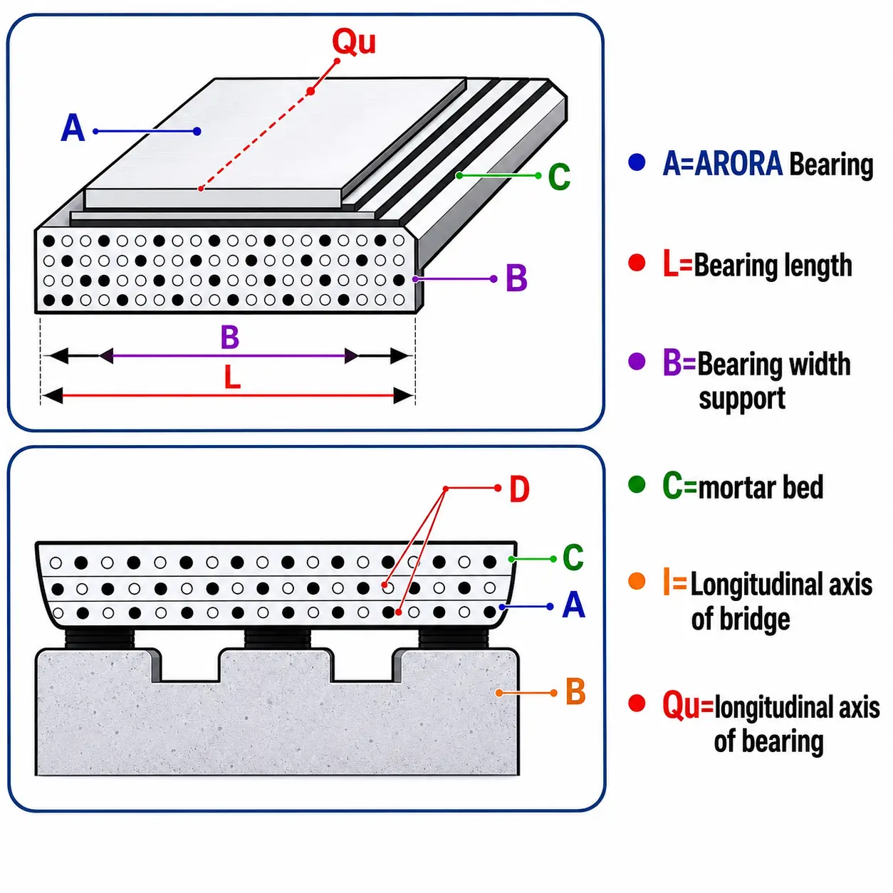
Internal steel laminates must align exactly with the technical specification parameters of **IS: 226**. Structural engineering scaling dictates that steel plate thickness changes require proportionate alterations in the inner elastomer matrix heights:
Outer cover elastomer layers (Top/Bottom) match half the individual inner thickness layer, capped strictly at a **6 mm maximum** boundary limit. **Side matrix cover** layers are verified continuous at **6 mm**.
Select a configuration tab below to inspect live structural load tolerances or verify raw rubber chemistry metrics under standard Indian Standard (IS) testing methods.
| Code Reference | Dimension (Overall L × W) | Thickness (Max) | Thickness (Min) | Design Load (Max) | Design Load (Min) |
|---|---|---|---|---|---|
| RSI 001 | 250 mm × 160 mm | 32 mm | 16 mm | 350 kN | 70 kN |
| RSI 002 | 320 mm × 160 mm | 32 mm | 16 mm | 460 kN | 90 kN |
| RSI 003 | 320 mm × 200 mm | 40 mm | 24 mm | 580 kN | 120 kN |
| RSI 004 | 400 mm × 200 mm | 40 mm | 24 mm | 730 kN | 150 kN |
| RSI 005 | 400 mm × 250 mm | 48/50 mm | 24/30 mm | 920 kN | 180 kN |
| RSI 006 | 500 mm × 250 mm | 48/50 mm | 24/30 mm | 1160 kN | 230 kN |
| RSI 007 | 500 mm × 320 mm | 90 mm | 48 mm | 1500 kN | 300 kN |
| RSI 008 | 630 mm × 220 mm | 65 mm | 48 mm | 1900 kN | 380 kN |
| RSI 009 | 630 mm × 400 mm | 84 mm | 48 mm | 2400 kN | 480 kN |
| RSI 010 | 800 mm × 400 mm | 84 mm | 48 mm | 3100 kN | 600 kN |
The implementation method for elastomeric bearings varies significantly depending on whether the superstructure is cast in-situ, precast concrete, or structural steel beams. Regardless of design, the lower and upper concrete mating surfaces must remain completely horizontal, parallel, clean, and flat.
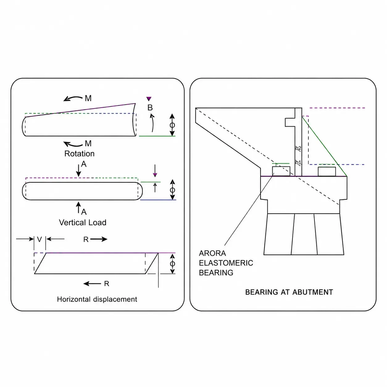
During cast-in-place execution, structural formwork barriers must be engineered to flawlessly prevent active concrete from weeping down and fouling the elastomeric bearing sides.
When structural elements are seated down onto laminated bearing pads, individual assemblies must be physically restrained from experiencing positional movement during launching stages.

Our engineering desk manufactures custom sizes exactly matching your project specifications. Submit your structural drawings or load parameters to receive an authenticated compliance quote.